High Pressure Die Casting
High Pressure Die Casting (HPDC) is a widely used manufacturing process where molten metal is injected into a steel mold cavity under high pressure and high speed, ensuring rapid solidification. This process is ideal for mass production as it allows for fast cycle times and consistent quality with reusable dies.
HPDC offers several benefits such as excellent dimensional accuracy, smooth surface finish, and the ability to produce thin-walled, lightweight components with complex geometries. It also reduces material wastage and machining requirements, making it highly cost- efficient for large-scale production.
Aganita has assisted High Pressure Die Casting (HPDC) companies to adopt casting simulation and reap benefits by prediction of casting defects, optimisation of gating design.
Designers can arrive at the ingate size and angle to achieve proper flow of melt; study the standing wave formation in the shot sleeve; determine the number & location of air vents and overflows; determine the impact of pressure intensification by conducting high pressure die casting (HPDC) simulation using ADSTEFAN.
Some of ADSTEFAN exclusive features for HPDC
Simulation along with Short Sleeve analysis
Simulation with Local Squeeze Pin
Die Temperature before Spray
Die Temperature After Spray
Above image shows molten metal flow behaviour in shot sleeve chamber for High pressure die casting process. Some of the casting defects such as air entrapment have their origins in the shot sleeve. ADSTEFAN has the unique feature to simulate the shot sleeve operations, and predict the standing wave formation in die casting.
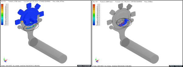
Above image represents air entrapment zones during filling of molten metal into die cavity. Blue region in simulation figure indicates air in the mold, and transparent color indicates liquid metal. Other colors indicate mixture of air and liquid metal with different mixture ratios. Highlighted regions are identified as potential air entrapment zones in casting
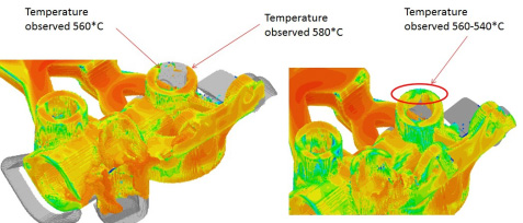
Figure shows the temperature of the melt during die cavity filling. Temperatures of the different streams of melt which meet and merge is visualised clearly by casting simulation of HPDC process. Specifically, if the temperature of the melt in any of the streams of flow becomes lower than the solidus temperature of the alloy, cold shut defect formation occurs. Casting simulation assists in prediction of the cold shut defect.
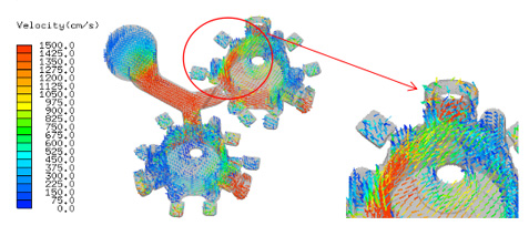
Figure above shows the velocity vectors in the melt region in the die cavity. The die erosion defect can occur in the regions of high velocity, especially in the corners and sharp edges in die. In the figure, the regions in the red arrows are characterised by high velocity and turbulent flow, where die erosion defect is highly probable. Visualising this by casting simulation, designer can optimise the gating to achieve lower velocities and overcome the die erosion defect.
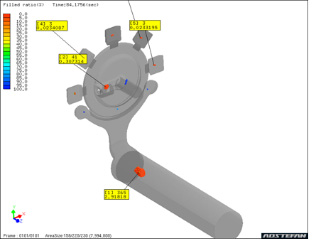
Figure above shows the formation of shrinkage porosity defect seen from HPDC simulation. There are many shrinkage porosity defects predicted in the die cast component.
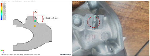
Figure shows shrinkage porosity occurring at a critical region in a die cast component. Size of the shrinkage porosity defect predicted by high pressure die casting simulation is seen to be around 3 mm. Right side figure shows the shrinkage porosity defect opening up during tapping process.
Above animation shows molten filling temperature distribution in HPDC process along with shot sleeve. Through this animation, design engineer can predict temperature distribution during filling and predict chances of cold shut/ misrun/ cold lap defects in casting
Above animation shows solidification pattern for HPDC process. Design engineer can understand gate and overflow cut off time and plan for further intensification to minimize porosity distribution in casting.


